Automated Spray Cleaning
SnoBot and CleanFlex
Small affordable (so-called) desktop robots were being introduced in the early 1990’s. While watching the movie Jurassic Park in a theater in 1993, I saw a small robot – called the Mitsubishi RV-M1 – being used to pick up, rotate, and place eggs in a dinosaur nursery incubator. Fascinated by the small robot operation, I quickly realized that this type of system would be the perfect automation solution for the new CO2 spray cleaning technology that I was just beginning to develop at the time. Shown in Figure 1-16, the first prototype SnoBot™ robotic CO2 spray cleaning system was developed by late 1995 using the RV-M1 robot. The SnoBot system featured an end-of-arm CO2 composite spray applicator equipped with a red light laser pointer to assist with teaching point-to-point CO2 spray cleaning paths using the built-in teach pendant and BASIC (Basic All-Purpose Symbolic Instruction Code) programming platform.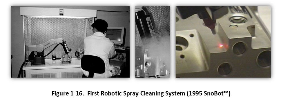
In 1997, work began with Mr. Lynn Liebschutz, IBM, San Jose, California, to develop CO2 spray cleaning processes to remove particle residues from spindle motors and other components used in hard disk drive (HDD) assembly. The initial cleaning applications involved components salvaged from new hard disk drives which failed during final assembly and test, and reworked for reuse in a new HDD assembly. The cleaning process proved very successful in manual cleaning operations using the MicroSno™ system in the IBM manufacturing plant in Ciudad Juarez, Mexico, but required automation to provide the productive capacity needed for the SE Asia plants. These operations produced a much larger volume of HDD component rework, including motor base assemblies (MBA) containing a spindle motor swage-mounted, magnets contained gaps and magnetically bonded particles, and drive covers with bonded filter elements. These HDD applications were exemplary of numerous cleaning applications for the CO2 composite spray technology over the years. The substrate could not be cleaned using wet methods – solvent or aqueous – due to complex device compatibility and fluid entrapment constraints. Dry automated CO2 spray cleaning was the only practical solution.
Shown in Figure 1-17, in 1999 collaborative work began with Lynn/IBM to develop a robotic pick-clean-place spray cleaning system. The system featured a Class 100 rated Mitsubishi RV-N series robot positioned between a replaceable tray for incoming contaminated product, a spray cleaning station, and a replaceable tray for outgoing cleaned product. The robot used a custom end effector to pick up a contaminated MBA from the incoming tray, move to a spray wash station to perform spray cleaning, and then place the cleaned component onto the outgoing tray. The spray wash station comprised a single stationary CO2 composite spray applicator positioned over a rectangular Plexiglas exhaust plenum, above which was situated a fan-blown ionizing HEPA air curtain.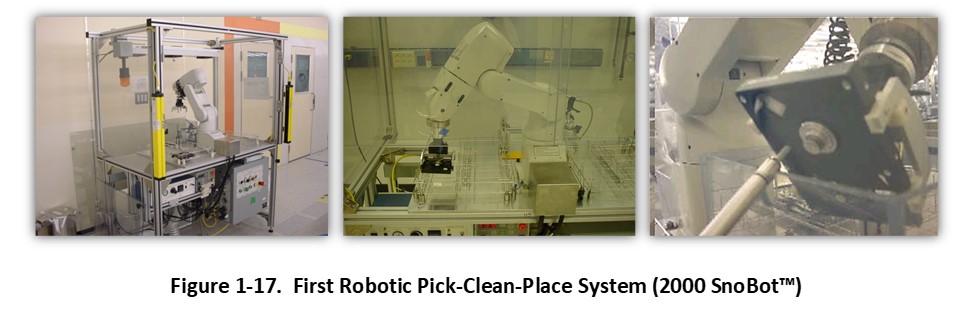
As shown in Figure 1-17, surfaces were selectively cleaned by articulating the component (i.e., MBA) in front of the spray applicator, during which the exhaust plenum extracted contaminated atmosphere containing the particles and residues detached from the MBA by the spray. The robot controlled the spray angle, spray distance, and surfaces to be cleaned. Using this scheme, the delicate features of certain portions of the component (i.e., ferrofluidic seal present on the spindle motor) could be selectively avoided. [Note: Future CO2 composite spray generator designs would allow for automatic spray power (thrust and particle size) reduction to allow for safe direct spray impingement.] Clean air flow over the MBA replaced the contaminated atmosphere during spray cleaning. This was accomplished using the suction produced by the exhaust plenum, drawing an adjustable volume and flow of ionized cleanroom atmosphere down over the cleaning station.
A “push-pull” air flow design was determined to be a very critical aspect for the performance of the CO2 composite spray cleaning process, and maintenance of the system cleanliness. CO2 composite spray cleaning of components possessing varying depths, edges, hidden surfaces, and other topographical features (complex geometry) produced highly turbulent, multidirectional, and variable speed airflow in the vicinity of the spray impinging the surfaces. Re-deposition of residues onto adjacent surfaces (as well as other components being cleaned and cleaning system surfaces) could be mitigated by simultaneously employing a relatively larger and more turbulent cross flow (relative to the CO2 composite spray(s)) comprising HEPA-filtered ionized air to create an open-cell micro-environment [33]. Unlike conventional laminar clean air flow systems with relatively low velocity and non-turbulent air flow, high velocity and turbulent clean ionized air flow behaved as a rinsing agent in the CO2 cleaning process.
The patented dry push-pull CO2 spray cleaning system operates in a way that is very similar to a conventional wet cleaning system using in-line washing, rinsing, and drying components. In an aqueous precision cleaning process, a contaminated substrate is first immersed in a wash tank (wet washing agent) to dissolve or otherwise entrain surface contaminants, following which the residual contaminated cleaning agent remaining on the various surfaces is removed using a turbulent or staged counter-flowing deionized water (wet rinsing agent) rinse tanks. Ultrasonic energy is often used to enhance the wet washing and rinsing process, and microfiltration is used to remove residual particulate matter from the wash and rinse agents. Most critical, a constant flow of deionized rinse water containing minimal background contamination (particulate, ionic, and carbon-based) is essential for optimal substrate cleanliness prior to precision drying operations. Contaminated deionized rinse water is filtered, re-processed using techniques such as reverse-osmosis, ion exchange, and activated carbon, and recycled back to the rinsing operation. During heated air blow-off drying, it is essential to use clean microfiltered air.
By comparison, an ultra-filtered CO2 composite cleaning spray (dry washing agent) chemically, physically, and selectively vectors contaminants from the various substrate surfaces into the surrounding ionized atmosphere (dry rinsing agent). This contaminated atmosphere is immediately removed from the cleaning zone and replaced with clean atmosphere, analogous to the aqueous rinsing process. The contaminated atmosphere is filtered downstream to remove the particulate and aerosol contaminants, and directly or indirectly recycled back into the spray cleaning zone. The clean ionized air rinsing process also mitigates surface charging during dry spray processing. As compared to wet cleaning processes, dry rinsing produces cleaner parts, faster. The push-pull design is utilized in all closed-cell CO2 composite spray systems.
In 2004, collaborative work began with Mr. Gary Knoth, Western Digital Corporation, San Jose, California, to design and develop a new high-capacity automated cleaning system that could clean both sides of multiple HDD rework components, including MBA, covers, and voice coil magnets (VCM). The first CleanFlex™ robotic CO2 spray cleaning system design was developed in cooperation with a contract equipment manufacturer - Semiconductor Process Equipment Corporation (SPEC), Valencia, California. Shown in Figure 1-18, a rotating carousel is positioned centrally with two (2) Adept cx600 SCARA (Class 10 rated) robots positioned inside and outside the carousel. Each robot uses an end-of-arm spray applicator with four (4) equal-spaced CO2 composite spray applicators supplied by two (2) Omega™ multi-channel spray generators. HDD rework 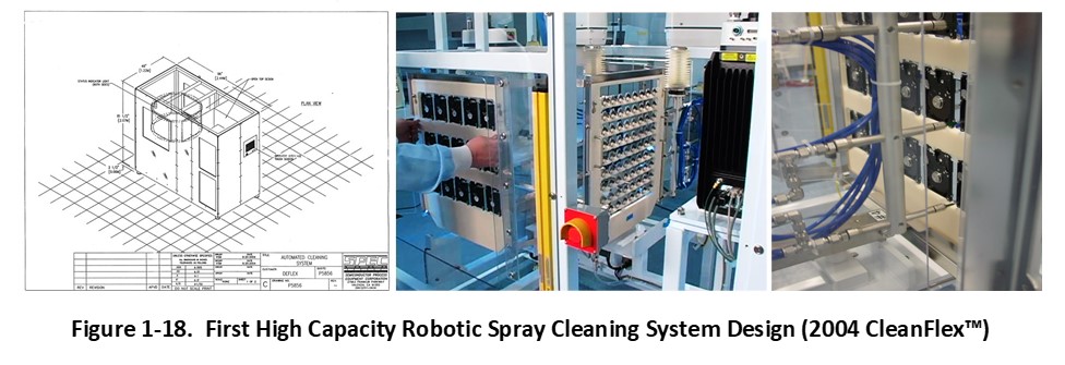
components are mounted on a removable static dissipative cleaning rack and placed onto a load station, following which the carousel automatically rotates and positions the rack between the two spray cleaning robots. Integrated control software recognizes multiple pallet types which allows various parts to be cleaned with discrete recipes and without operator interface. Cleaning recipes (programs) are stored within the robot controllers and allow for adjustments of cleaning speeds, spray angles, overlap spacing, and distance from spray nozzle to surface.
The CO2 composite spray cleaning process is effective for removing submicron particles as small as 0.1 microns in controlled environments, and can remove even smaller particles if special attention is paid to the quality of the surrounding atmosphere (i.e., use nitrogen-purged micro-environments) and ultraclean fabrication techniques for the spray generator. Testing with the new system demonstrated that it could exceed the particle cleanliness specification using a single pass cleaning recipe and could clean to lower levels using multiple cleaning passes. Besides spray performance, the carousel-based robotic spray platform dramatically changed the economics of HDD parts cleaning. With a footprint of approximately 6x8 feet, HDD parts could be precision dry cleaned in high volume using a fraction of the (expensive) cleanroom floor space allocated to comparable aqueous cleaning lines and with a cost-per-clean part reduction of between 50% and 80% [34].
Shown in Figure 1-19, robotic spray cleaning designs progressively improved over time. The latest robot-automated spray cleaning system, called Vulcon Ice™, was introduced in 2014. This new carousel-style platform utilizes dual robots equipped with the latest CO2 composite spray generation and spray quality monitoring technology – GENESYS™ Pro and LightSPEC™ – capable of precision dry cleaning tens of thousands of rework or prime hard disk drive components per day.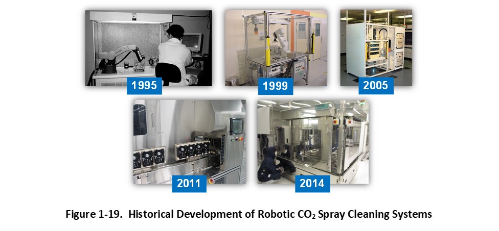
In retrospect, the HDD industry has been the principal driving force for the development of automated CO2 composite spray cleaning technology. Unique cleaning problems in terms of both part complexity and stringent cleanliness standards combined with very high volume cleaning requirements have driven significant advancement of CO2 composite spray generation, delivery, and automation in terms of spray capacity, stability, economy, power, and quality control.
References:
- 1-33. U.S. Patent 6,656,017, D. Jackson, Method and Apparatus for Creating an Open-Cell Micro-Environment for Treating a Substrate with an Impingement Spray, December 2, 2003
- 1-34. Automated CO2 Composite Spray Cleaning System for HDD Rework Parts, G.W. Knoth et al., Journal of the IEST, Volume 52, Number 1, April 2009


Ready for next steps? Try our CO2 Powered Consultation.