CO2 Composite Spray
Pencil Snow Blaster
Concurrent with centrifugal liquid CO2 immersion cleaning process commercialization, development of a new CO2 spray cleaning technology also began in the early 1990’s. CO2 spray cleaning is a selective line-of-sight surface cleaning process. The first precision CO2 spray cleaning system, called the SNOGUN™, was developed by Dr. Stuart Hoenig, Arizona State University in the mid-1980’s [27]. The SNOGUN innovation was refined by Hughes Aircraft (and many others) in the 1990’s. My interest in the SNOGUN was that a CO2 spray cleaning process complements a CO2 immersion cleaning process. Analogous to conventional solvent vapor degreasers, a CO2 spray (wand) provides a final clean or rinse step to remove thin films and micro-particulate contamination following general cleaning using centrifugal liquid CO2 immersion processes.
In 1993, I purchased a SNOGUN from Va-Trans, Chula Vista, California. Shown in Figure 1-10, precision cleaning application development using this system proved somewhat difficult absent a nitrogen-purged glove box. Spray energy could be controlled using a built in metering flow control valve (topside of SnoGun, Fig. 1-10), however spray cleaning energy decreased with decreased CO2 mass flow. One particular cleaning constraint was atmospheric condensation of water vapor, particles, salts, and hydrocarbons onto substrates during spray operation. The dry ice particle-gas aerosol, absent mitigating control measures, electrostatically charged, entrained, and condensed the surrounding atmosphere. This necessitated the use of a nitrogen-purged glove box or minienvironment, infrared heater, and ionized air. A new method was needed that could provide a precision CO2 spray independent of particle concentration and with additional heat capacity – similar to the spray methods used in CO2 pellet ice blasting but using smaller CO2 particles (and process additives) generated in-situ.
An early experiment to enhance the performance of the spray process involved centrally positioning a small CO2 capillary within a Coanda air amplifier. This experiment demonstrated that a CO2 particle stream ejected from a small capillary tube could be adjustably accelerated or decelerated simply using air pressure driving the Coanda air amplifier, and the additional Coanda air flow somewhat mitigated condensation by providing improved drying action. However, this first experiment proved too bulky and unable to significantly improve spray cleaning energy. More power and heat was needed to intensify and optimize the CO2 spray cleaning process.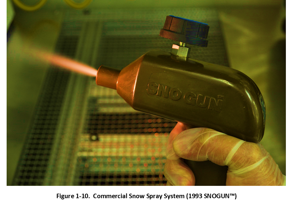
While attending the Westec Convention, Los Angeles, California, in March 1994, I came across a product called the Micro Blaster®, manufactured by Comco Inc., Burbank, California. The Micro Blaster is a benchtop precision microabrasive blast (MAB) cleaning system that sprays a composition of surface-ablative particulates such as sodium bicarbonate, wood, glass, or ceramic entrained in air propellant. A pressurized canister of microabrasive particles is fluidly connected to an airstream and delivered using a long flexible polymeric tube and applied using a handheld spray applicator. Particle spray power is adjusted using particle hardness, size, mass flow, and air pressure, as well as specially designed carbide-tipped particle-air mixing nozzles. The Micro Blaster also featured a lighted workstation and HEPA vacuum system for capturing the dusts and ablative by-products generated during the spray treatment process. Watching Mr. Neil Weightman, President, operate the Micro Blaster system immediately connected several dots and work began to develop a new type of CO2 precision spray cleaning process – a CO2 composite spray.
Shown in Figure 1-11, a prototype CO2 composite spray cleaning system called the “Pencil Snow Blaster” using a new thermal ionized gas snow (“TIG-Snow”) spray process was constructed, tested, and exhibited at the 1995 Westec Convention. The new system featured a pulse-injected CO2 particle spray supplied from a PEEK capillary positioned coaxially within a secondary polymeric propellant tube. The PEEK capillary injected a CO2 particle-gas stream for a pre-determined period of time into a pressure- and temperature-regulated ionized air propellant stream. A mixing nozzle was used to adjust the size of the CO2 particles (expansion cooling process) and to mix the particles into the heated propellant to form an adjustable CO2 spray cleaning composition. Pulsed CO2 injection with heated and ionized propellant gas significantly controlled surface freezing, atmospheric condensation, and electrostatic charging issues common to conventional Snow Guns. The first patent application for this new spray cleaning system was filed in 1995 [28].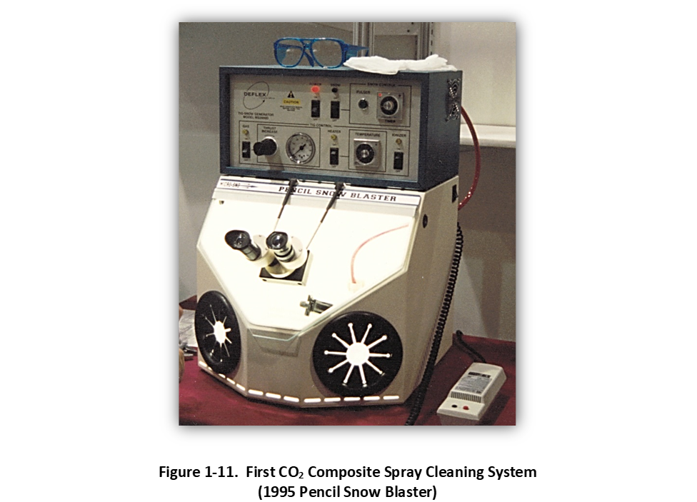
Shown in Figure 1-12, the first commercial benchtop CO2 Composite Spray cleaning system (manufactured under the tradename MicroSno™ by Comco Inc.) was introduced in 1996 at the Precision Cleaning Expo in Chicago. MICRO magazine acknowledged the MicroSno™ as a Top 40 new product for 1996. The new spray system featured a new rear-mounted 18-turn micrometering valve to adjust the mass flow of CO2 particles into the coaxial spray applicator during pulsed injections. This feature provided better condensation control as well as enhanced cleaning. It was noticed during applications development that leaner (less particle dense), hotter, and higher propellant pressure sprays produced drier and cleaner parts, faster. This observation would be later optimized in future spray cleaning system innovations. Exemplary commercial applications developed for the first generation CO2 composite spray cleaning system are described in articles published in Precision Cleaning Magazine in 1999 [29-30].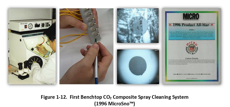
The historical development of the CO2 composite spray system is shown pictorially in Figure 1-13. Commercial system designs and processes improved with more consistent and continuous (non-pulsed) cleaning sprays as well as more productive cleaning capacity using multiple sprays and automation.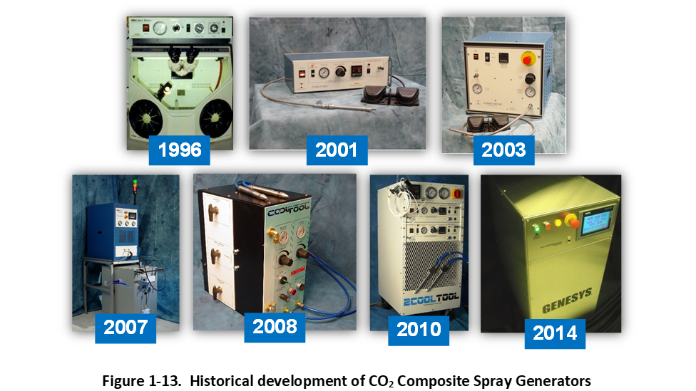
Shown in Figure 1-14, CO2 composite sprays evolved from a single handheld pulsed spray cleaning applicators to leaner and multiplexed continuous spray applicators. Second generation system designs improved the basic spray process with higher propellant temperatures, improved CO2 purification and condensation processes (liquidàsolid), and spray generation control - featured in commercial products PowerSno™ and OMEGA™ [31].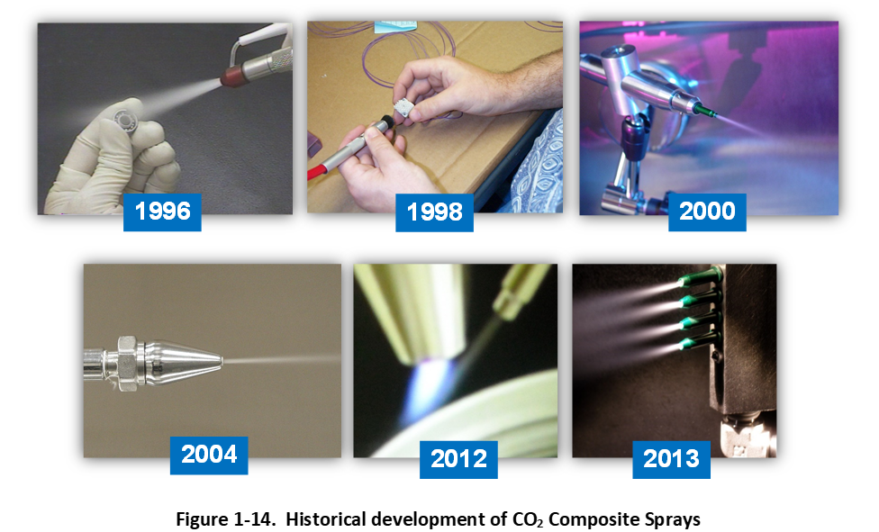
More recently in 2013, a third generation CO2 composite spray technology was developed which utilizes a supercritical micronization process to produce a uniform, dense, and high surface area CO2 particles-in-air aerosol spray [32]. This latest spray technology utilizes a fraction of the CO2 as compared to the previous generation and produces cleaning (and cooling) sprays having much higher spray power.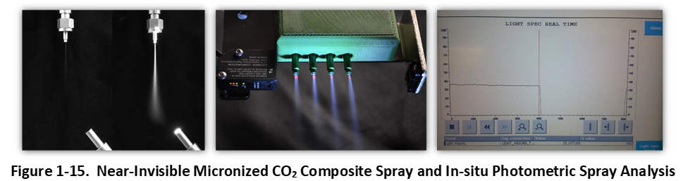
Moreover, shown in Figure 1-15, a new photometric spray monitoring technology was co-developed and integrated with the micronized spray which allowed for real-time and in-situ analysis of spray geometry to monitor, maintain, or dynamically change key CO2 spray process variables (particle injection rate, propellant pressure and temperature) during application – featured in the commercial product GENESYS™ [33]. The micronized CO2 spray technology utilizes a minimum amount of CO2 to produce an ultra-stable and uniform spray that produces the fastest cleaning rates and most consistent part-to-part cleanliness levels to date.
References:
- 1-27. Cleaning Surfaces with Dry Ice, S.A. Hoenig, Compressed Air Magazine, August 1986, pp 22-25
- 1-28. U.S. Patent 5,725,154, D. Jackson, Dense Fluid Spray Cleaning Method and Apparatus, March 10, 1998
- 1-29. Using CO2 Snow to Correct Drive Level Dependence in Quartz Crystal Resonators, R.C. Chittick, Precision Cleaning Magazine, Vol. V, No. 6, June 1997
- 1-30. Today’s Forecast: It looks like Snow, D. Jackson et al., Precision Cleaning Magazine, Vol. VII, No. 5, May 1999
- 1-31. U.S. Patent 7,451,941, D. Jackson, Dense Fluid Spray Cleaning Process and Apparatus, November 18, 2008
- 1-32. U.S. Patent 9,221,067, D. Jackson et al.,CO2 Composite Spray Method and Apparatus, December 29, 2015
- 1-33. U.S. Patent 9,227,215, D. Jackson et al., Determination of Composition and Structure of a CO2 Composite Spray Method and Apparatus, January 5, 2016


Ready for next steps? Try our CO2 Powered Consultation.