Centrifugal Liquid CO2 Immersion
SuperFuge™
Design and development of a new high performance dense fluid immersion cleaning system began in late 1989. Previous studies at Hughes comparing the cleaning rates and efficacy between scCO2 and liquid CO2 showed that – although not as effective as scCO2 for certain polar or more complex (waxy) contaminants – liquid CO2 demonstrated higher contaminant carrying capacity and faster cleaning rates, particularly for non-polar oily hydrocarbon and silicone contaminants. Lack of solubility for a particular contamination was easily remedied with the addition of a suitable liquid CO2 fluid modifier (2% to 5% by vol.) comprising various mixtures of non-ionic surfactants (i.e., Dow Triton® X-15) dissolved in a carrier solvent such as a paraffin, ester, or alcohol. Moreover, mechanical processing of substrates using liquid CO2 in static or impeller-mixed fluid reactors was more challenging, particularly during the depressurization sequence. During vessel depressurization, localized pool boiling and subcooling of liquid CO2 trapped within small cavities and pores caused dry ice formation and/or precipitation of dissolved contaminants from solution and recontamination of substrate surfaces. Several fill-drain cycles or continuous fluid flow with external separation, as well as a post-process substrate heat-up cycle was required before removing substrates from the processing chamber to meet the cleanliness objectives. These extra steps added significant time to complete the cleaning-extraction process.
Given these opportunities and constraints, a primary objective was to develop a faster and more efficient liquid CO2 immersion cleaning (and fluid recycling) process for commercial production applications involving relatively larger volumes of tightly packed substrates for example a basket full of oily precision machined components. Shown in Figure 1-6, a hand-drawn sketch made by our design engineer (and father), Richard W. Jackson, during Thanksgiving 1989 depicted the basic components of a new “high energy” liquid CO2 cleaning system concept called DEnse FLuid EXtraction or simply DEFLEX system. 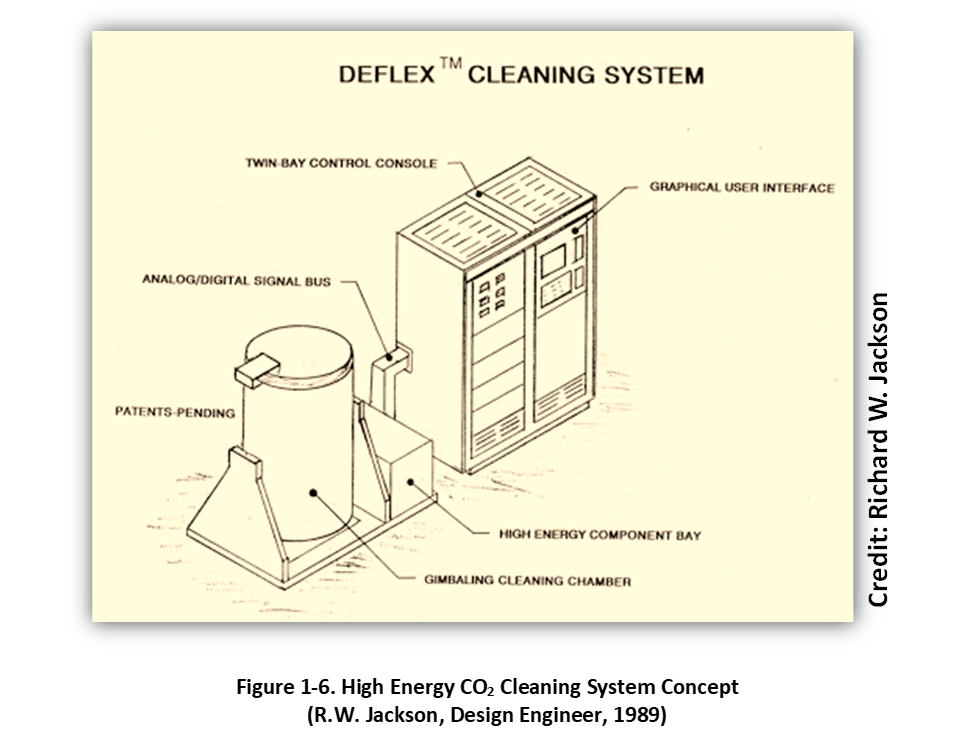
The use of high energy, analogous “process intensification”, related to measures that make the cleaning process more efficient. I had some ideas about potential high energy sources (i.e., microwaves, ultrasonics) but a lot of experimentation was needed and several CO2 process intensification schemes were investigated between 1989 and 1993.
The application of ultrasonic cleaning energy was common to aqueous and Freon® 113 immersion cleaning processes. It seemed fairly straightforward to apply ultrasonics to dense phase CO2. An ultrasonic-assisted precision cleaning process was developed using a small titanium ultrasonic horn (Sonics and Materials Vibra Cell) inserted into and affixed to a threaded port of a 1-liter high pressure vessel using a nut and ferrule assembly compressed into the node (zero vibration position) of the horn. Tests performed with liquid CO2 showed that it needed to be supersaturated (nearly incompressible) to enable very limited and localized cavitation. The vessel was pressurized with liquid CO2 to above 1200 psi, following which pulsed ultrasonic energy was applied. Initial application development for the ultrasonic-assisted CO2 cleaning method involved oily precision instrument bearings. It was found that the cavitation effect was very short range and that improvement in the cleaning rate could be achieved only by positioning the contaminated bearings in very close proximity to the titanium horn.
A bit discouraged with the ultrasonic high energy approach for cleaning large volumes of substrates, I remembered a paper I had read at Hughes regarding a new microwave-assisted solvent extraction process for obtaining valuable compounds from plant materials. The microwave-assisted extraction process used various non-polar solvents (microwave transparent) and in the presence of microwave radiation the plant material and polar constituents were heated within the solvent to enhance diffusion and solubility of the extracts. This process seemed a very promising approach for non-metallic substrate processing such as polymeric substrate extraction in liquid CO2. A microwave-assisted extraction process was developed utilizing a modified microwave oven as a processing platform. The microwave oven contained a microwave-transparent thick-walled polymeric pressure vessel with a threaded closure and Teflon O-ring seal, and high pressure tubing and fittings all of which was adapted from conventional designs used in microwave-aided acid digestion and solvent extraction systems and processes. The dense fluid delivery system used small diameter microwave-transparent polyetheretherketone (PEEK) high pressure tubing and fittings fed through small holes drilled into the back of the oven to provide a continuous flow of liquid CO2 into and out of the small extraction vessel during microwave processing. Microwave energy at various power settings was used to selectively heat a small pre-weighed polymeric coupon immersed in liquid CO2. The microwave-intensified extraction process demonstrated an increase in total mass loss rate as compared to Soxhlet extraction procedures used in the past. The microwave high energy extraction process proved somewhat successful but was not scaled up to a production system due to its limited utility for most cleaning opportunities at the time, particularly degreasing precision machined metal parts [17].
In 1991, my day job was an environmental engineering consultant working for EMCON Associates (Burbank, California) while moonlighting the CO2 process development work in my garage. I provided waste minimization and wastewater treatment support services to companies with EPA-regulated metal finishing and electroplating lines, and wastewater discharges requiring specialized treatment technology to remove heavy metals, cyanides, and suspended solids. I had the opportunity to observe and work hands-on with numerous metal finishing and electroplating systems and processes. In this regard, barrel plating and centrifugal wringing were very interesting processes. The equipment used in both processes involved changing the position and orientation of the substrates in space relative to a fluid (water, air) with the application of gravitational and centrifugal forces, and with adjustable rotational velocity and direction, to provide uniform surface coverage, drainage, and removal (and recovery) of electroplating solutions or rinse waters trapped in cavities of small machine parts such as gold-plated or cadmium-plated connector pins and housings. These observations connected the dots for me – and became the basis for the development of the new production-capable high energy process called centrifugal liquid CO2 cleaning.
A small-scale centrifugal CO2 cleaning system was constructed using an AC-inverter speed controlled electric motor attached to a belt-driven magnetic mixer. The magnetic mixer drive shaft was inserted into and sealed to a 1L pressure vessel using a threaded fitting. A small centrifuge drum adapted from a very small polymeric meshed basket used in barrel plating processes was attached to the magnetic drive shaft using a threaded adaptor. Cleaning tests with various contaminated substrates – including oily screw-machined connector pins and silicone polymers – confirmed the enhanced cleaning performance of the new centrifugal CO2 cleaning process. The pressure vessel was filled and drained repeatedly with liquid CO2 to mimic an immersion and draining process during which centrifuge speed and direction were both controlled, upwards of 1000 rpm. In addition, the cleaning vessel could be operated in a vertical (high speed basket centrifuge) or horizontal (tumbler) orientation to assist with fine particle and chip removal (i.e., connector pins).
The new centrifugal CO2 process addressed mass flow, solvent carrying capacity, and surface access constraints associated with the very low viscosity and surface tension liquid CO2, and particularly for complex cleaning applications. Importantly, the centrifugal CO2 cleaning process resolved dry ice formation during depressurization which mitigated recontamination issues [18-19].
In 1993, construction began to develop a full-scale prototype centrifugal CO2 cleaning system and a CO2 recycling module. The prototype would become the basis for future commercial centrifugal CO2 immersion cleaning system designs and is shown in Figure 1-7 with my software development engineer (and brother), Rick Jackson, at the control console. In the Spring of 1994, the prototype system was moved to our CO2 pump supplier’s location - Haskel International, Burbank, California - where it was demonstrated live to several California environmental agencies including the regional environmental protection agency (Cal-EPA), regional water quality control board (RWQCB), and south coast air quality management district (SCAQMD) in Burbank, California [20].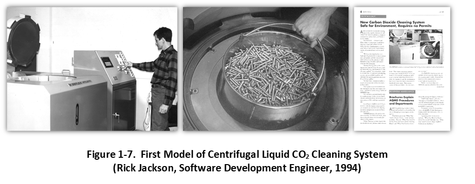
As a result of this demonstration, the following year the new centrifugal liquid CO2 cleaning technology was evaluated by the USEPA under a cooperative agreement with Research Triangle Institute (RTI), Research Triangle Park, NC. In 1995, a new commercial centrifugal CO2 cleaning system called the SuperFuge™, shown in Figure 1-8, was shipped to Warner-Robins Air Logistics Center (WR-ALC), Robins Air Force Base (RAFB). Two of our company engineers, Mr. Fred Chen and Mr. Randy Rutledge, accompanied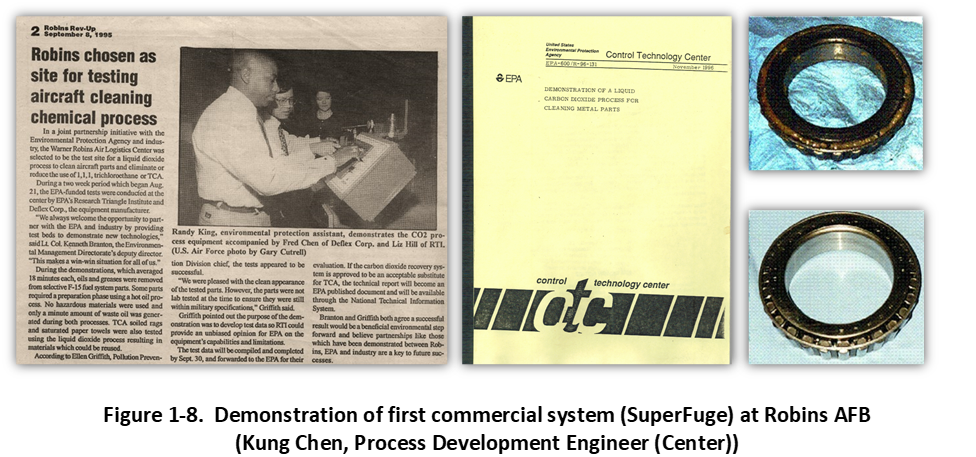
the system to provide technical support for the demonstration project. The RAFB evaluation demonstrated a new two-step wash-rinse process using a high-boiling solvent prewash agent called HOP or Hot Oil Pretreatment to remove gross particles, chips, and other soils followed by a centrifugal liquid CO2 rinsing cycle to remove (and recover) residual prewash solvent and contaminants. Suitable high boiling prewash agents (relative to CO2) included many compounds already inventoried by an end-user or considered environmentally benign, for example straight machining oils, Stoddard solvents, and high boiling alcohols and terpenes. In this closed-loop process, both the prewash fluid and liquid CO2 rinse agent were recycled and reused in-situ. Several aircraft maintenance cleaning applications were successfully demonstrated, including F-15 aircraft wheel bearings, fasteners, washers, as well as oil-contaminated shop maintenance cloths and mops. The project detail and results are described in a published article in September 1996 and a U.S. EPA report published in November 1996 [21-22].
The historical development of Centrifugal CO2 systems is shown pictorially in Figure 1-9. All of the commercial products utilized the basic multi-step cleaning process developed for the RAFB application, and was used extensively in commercial cleaning applications development in the 1990’s. This process comprised an ultrasonic HBS prewash procedure absent centrifugal energy or a HBS immersion prewash procedure using bi-directional centrifugal washing, followed by a centrifugal wringing process to remove gross HBS, and finally completed using a multi-stage bi-directional centrifugal liquid CO2 rinse cycle.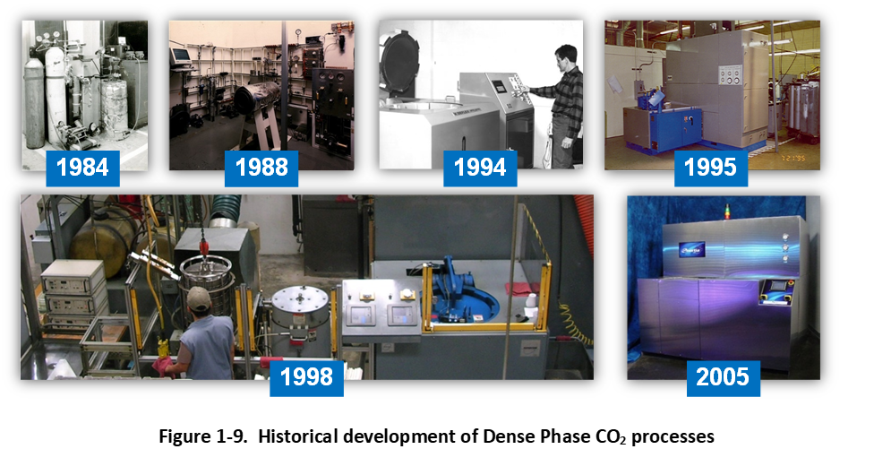
Applications involving small complex machined substrates (i.e., screw-machined ball point pen tips) containing fine metal chips were first washed using a HBS prewash agent such as a straight machining oil already in use or a substitute machining oil. Using this waste minimization approach, the prewash agent served both machining and cleaning process functions. Following the prewash cycle, the substrates were drained or centrifugally wrung to remove and recover gross HBS prewash agent. Finally, the HBS-wet substrates were rinsed using a centrifugal liquid CO2 process step. This implementation scheme increased productivity, substrate and system cleanliness, and overall efficiency of the precision cleaning process. In applications involving substrates absent significant physical contamination such as silicone oils, particles, and chips, as well as cleaning capacity constraints, the prewash and rinse process was implemented within the same centrifugal system.
Later process developments involved a CO2-expanded high boiling solvent (HBS) prewash agent. Pressurizing the HBS prewash agent with CO2 (gas, liquid and supercritical) enhanced centrifugal cleaning by lowering viscosity and surface tension, and improving drainage of the HBS prewash agent. This was evidenced by a significant increase in the centrifuge stall (magnetic drive torque and breakaway) speed as the HBS was pressurized with CO2. Moreover, the presence of multiple solvent phases improved particle cleanliness and solute carrying capacity of the solvent system. Still moreover, it was discovered that high pressure CO2 gas expansion of the HBS prewash agent clarified or flocculated dissolved and suspended contaminants in the HBS prewash agent, providing solvent washing or anti-solvent processing. Using only microfiltration allows the prewash agent to be used for an extended period of time. Early commercial installations and applications for the SuperFuge™ centrifugal liquid CO2 cleaning system and process are described in an article published in Parts Clean Magazine in April 1999 and Process Cleaning Magazine in 2009 [21-22]. Later commercial centrifugal cleaning system designs and processes were improved with a CO2-expanded HBS prewash (so-called “Tunable Solvent” system), faster top-loading bi-directional centrifuge drum with removable basket, and a faster and more efficient dense fluid recycling processes [25-26].
References:
- 1-17. U.S. Patent 5,213,619, D. Jackson and M. Lepp, Processes for Cleaning, Sterilizing, and Implanting Materials using High Energy Dense Fluids, May 25, 1993
- 1-18. U.S. Patent 5,344,493, D. Jackson, Cleaning Process using Microwave Energy and Centrifugation in Combination with Dense Fluids, September 6, 1994
- 1-19. U.S. Patent 5,368,171, D. Jackson, Dense Fluid Microwave Centrifuge, November 29, 1994
- 1-20. New Carbon Dioxide Cleaning System Safe for the Environment, Requires no Permits, AQMD Advisor, July 1994, p 4
- 1-21. Demonstration of Liquid CO2 as an Alternative for Metal Parts Cleaning, Charles Darvin, et al., United States Environmental Protection Agency (USEPA), Precision Cleaning Magazine, Volume IV, Number 9, September 1996
- 1-22. Demonstration of a Liquid Carbon Dioxide Process for Cleaning Metal Parts, E.A. Hill and K.R. Monroe, Research Triangle Institute, EPA-600/R-96-131, November 1996
- 1-23. Liquid CO2 Immersion Cleaning: The User’s Point of View, D. Jackson et al., Parts Cleaning Magazine, April 1999, pp 33-37
- 1-24. CO2 for Complex Cleaning, D. Jackson, Process Cleaning Magazine, July/August 2009, pp 32-37
- 1-25. U.S. Patent 6,802,961, D. Jackson, Dense Fluid Cleaning Centrifugal Phase Shifting Separation Process and Apparatus, October 12, 2004
- 1-26. U.S. Patent 7,601,112, D. Jackson, Dense Fluid Cleaning Centrifugal Phase Shifting Separation Process and Apparatus, October 13, 2009


Ready for next steps? Try our CO2 Powered Consultation.